Thursday, 6 March 2014

Wednesday, 29 January 2014
Booster 2SC2630 For FM Broadcast

Wednesday, 9 March 2011
Wednesday, 8 September 2010
Back Pack Radio transmitter civil version. (manpack radio)
One off model Q-Mac backpack transmitter made in Australia, its very simple and user friendly.Bravo sierra base, this is mike mobile 8, do you read me...over...
I have one when i was still join at one off UN agency in Aceh....
This transmitter only 50 watt power with battery pack and you can send sell call to different brand like Codan Transmitter.

Thursday, 2 September 2010
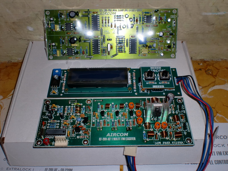
1 Watt simple FM transmitter for nice broadcast


My Old Homebrew 3,0 Mc to 3,8 Mc Final Tube 807's
The frequency working from 3.0 Mc to 3,8 Mc.I'm loved my homebrew.Now I put the transmitter is no longer, because I do not have enough time, but still I keep it, probably because at that time to assemble, I was forced to work part time to buy a rather expensive components.
I used open dipole 1/2 lambda antenna.Its good working for 1000km distance.
73 88 cherio
YC6CIT/Batara siwa
First model
Oscillator Tube 6V6 coolpits
Buffer 6L6
Final 2 x 807
with pi section filter antenna system.
Voice DSB
Power 125 watt


My second model
Oscillator 12BY7 with coolpits I put under chasing.
Buffer 6L6
Final 2 x 807 with Coil Induction Antenna
Sometime I change the tube with 6146 RCA.Socket still use 807 but I made socket adapter .
Transformer PT 300, 600V CT


Sunday, 1 August 2010
Install HF trannsmitter (codan) at Fishing boat Simeulu Island, Indonesia
in this emergency situation, many people at teluk dalam don't have foods and water. .
The radio must installing at the boat, because mobile phone is not functions.

Sunday, 29 November 2009
My codan Antenna is broken


Monday, 20 April 2009
Automatic tuning antenna|Control cable


Wednesday, 28 January 2009
Satellite Phones for emergency response

Iridium Phones
Go anywhere!
Iridium’s satellite network is the only truly global communications network providing voice, paging, 160-character two-way short text messaging (SMS), emergency 911 service (dial sequence 00-911) and internet access services to subscribers anywhere on the surface of the earth. Even the polar caps have Iridium coverage!
The Iridium 9505A is smaller, more power efficient and more water resistant than the ground-breaking original Iridium phone, The internet access is 2400 bps (direct dial circuit switched) or 10,000 bps* with our free SkyFile compression and email software. Includes: Iridium 9505, universal AC charger and international plug kit, high cap battery, mag-mount car antenna (with 1.5 meter cable), antenna adapter, DC charger, belt holster, hands free earpiece, and manual.
Options: external mast antennas (U-bolt and thread mount types), antenna cables, mag-mount vehicular antennas, high capacity batteries, external battery packs,watertight Pelican impact case, portable solar chargers, and fixed-site Iridium phones for PBX applications
Wednesday, 18 June 2008
Load my Towers

 Look at my towers antenna, very full of many radios antenna model and internet link.look like snake heheheh
it's very danger if any speed win...
my bos don't want to change this tower, because we don't have budget :)
I have UHF, VHF, HF and Internet link.
Monday, 25 February 2008
ICOM T90A

The commercial grade Icom T90A transmits on 6 meters, 2 meters and 440 MHz. The T90A is also a wide band AM, FM and Wide FM scanning receiver. Not only can you hear your favorite TV programs (until 02/14/09) with the preprogrammed TV channels, but you can also listen to short-wave, AM and FM broadcast radio stations, police, fire, military, aircraft, various amateur bands and more. Receive coverage is 495 kHz to 999.990 MHz (less cellular). With 500 alphanumeric memory channels, plus 50 band edges and 5 call channels, the IC-T90A is a dream radio! But, with ICOM's new DMS (Dynamic Memory Scan) technology, the IC-T90A makes the dream a reality. With the maximum of 18 banks or 99 channels per bank, you can pick and choose any desired channel for scanning from 500 available memories. This compact radio is comfortable in the smallest of hands, and offers full radio control for large fingers. The rugged die-cast aluminum chassis is designed for the most demanding environments with JIS-4 specification for weather resistance.
A standard feature of the IC-T90A is both DTCS and CTCSS encode and decode capability. Don't know what tone is used? Don't worry; the tone scan feature will identify the appropriate tone frequency. Choose from either 104 DTCS or 50 CTCSS codes for receive and transmit, individually. The new Weather Alert Scan capability checks active weather stations for NWS alert activity even while you monitor local repeater communications.
Simple, one-handed operation is the most valuable feature of the IC-T90A. The backlit ten-key pad allows you to enter frequency, memory number and various other features. While the tuning knob can be customized for either channel selection or volume control. There is no cumbersome function key on the T-90A!
The T90A operates from 6 to 16 VDC and is only 2.3x3.5x1.25 inches 8.5 oz (58x87x29mm 240g). The ICOM T90A comes with a BP-217 Li-Ion battery, BC110A wall charger, wrist strap, MB-83 Swivel belt clip and SMA flexible antenna (with 6m adapter). An informative owners manual is included along with a separate Ham Radio Terms manual. Please see the January 2003 issue of QST for a great review on this easy-to-use HT!
| |
Motorola GR1225 Repeater (VHF-50Watt) [H5158]
| Frequency range: 146-174Mhz | ||||
| ||||
|

Motorola GR500
Product Description
Motorola GR500 FeaturesThe GR500 has the following features: • Modular Design - Allows quick field replacement of disabled components. ApplicationsThe GR500 repeater can be used for a variety of applications. Here are a few examples of some key industries:
Motorola GR500 Repeater ModelsThe GR500 has a 7 Step Ordering Process due to the number All GR500 repeaters include the following: • Field Programmable AccessoriesControllers/Add-On Modules Basic Interface - Provides repeater functionality, remote knock-down/set-up, in/cross band and uni/bi-directional capabilities. I20R Onsite Repeater - Provides up to 10 PL/DPL single-code or cross-code combinations for multiple group repeater operations, remote knock-down/set-up, in/cross-band and uni/bi- directional capabilities and CWID (Morse code). The I20R also provides battery power alert tones and Radio Service Software programming. ZR310 Multiple Tone Community Repeater - Adds up to 50 PL and 20 DPL single-code or cross-code combinations and enhanced community repeater operator capabilities. I50R Basic Interconnect - Adds basic interconnect and remote knock-down and set-up. ZR340 Advanced Interconnect - Adds advanced interconnect features such as prestored telephone numbers, access/override access codes, dialing restrictions, call timers, direct-air access and CWID. ZR320 Selective Calling Interconnect - Provides revertive PL/DPL/Quik-Call group or individual selective calling, CWID and advanced interconnect capabilities. I750R Selective Calling Interconnect - Provides revertive PL/DPL/Quik Call II/MDC-1200 group or individual selective signalling and advanced interconnect capabilities such as prestored telephone numbers, access/override access codes, dialing restrictions, call timers, direct-air access and CWID. SmarTrunk II - Requires RadiusPort radios to be equipped with SmarTrunk II Advantage Boards. Provides trunked repeater functionality, group calling, individual selective calling, advanced interconnect calling and airtime accumulation capabilities. TRA100R Tone Remote Adapter - Provides remote knock-down/set-up and tone remote capabilities for remote access and control of repeaters using the MC series tone-remote desksets. |

Tuesday, 14 August 2007
Coaxial cable

Coaxial cable or is an electrical cable consisting of a round conducting wire, surrounded by an insulating spacer, surrounded by a cylindrical conducting sheath, usually surrounded by a final insulating layer (jacket). It is used as a high-frequency transmission line to carry a high-frequencybroadband signal. Because the electromagnetic field carrying the signal exists (ideally) only in the space between the inner and outer conductors, it cannot interfere with or suffer interference from external electromagnetic fields.
Description
Coaxial cables may be rigid or flexible. Rigid types have a solid sheath, while flexible types have a braided sheath, usually of thin copper wire. The inner insulator, also called the dielectric, has a significant effect on the cable's properties, such as its characteristic impedance and its attenuation. The dielectric may be solid or perforated with air spaces. Connections to the ends of coaxial cables are usually made with RF connectors.
Signal propagation
 Radio-grade flexible coaxial cable. A: outer plastic sheath B: copper screen C: inner dielectric insulator D: copper core
Open wire transmission lines have the property that the electromagnetic wavecharacteristic impedance. They also cannot be run along or attached to anything conductive, as the extended fields will induce currents in the nearby conductors causing unwanted radiation and detuning of the line. Coaxial lines solve this problem by confining the electromagnetic wave to the area inside the cable, between the center conductor and the shield. The transmission of energy in the line occurs totally through the dielectric inside the cable between the conductors. Coaxial lines can therefore be bent and moderately twisted without negative effects, and they can be strapped to conductive supports without inducing unwanted currents in them. In radio-frequency applications up to a few gigahertz, the wave propagates only in the transverse electric magnetic (TEM) mode, which means that the electric and magnetic fields are both perpendicular to the direction of propagation. However, above a certain cutoff frequency, transverse electric (TE) and/or transverse magnetic (TM) modes can also propagate, as they do in a waveguide. It is usually undesirable to transmit signals above the cutoff frequency, since it may cause multiple modes with different phase velocities to propagate, interfering with each other. The outer diameter is roughly inversely proportional to the cutoff frequency. propagating down the line extends into the space surrounding the parallel wires. These lines have low loss, but also have undesirable characteristics. They cannot be bent, twisted or otherwise shaped without changing their
The outer conductor can also be made of (in order of decreasing leakage and in this case degree of balance): double shield, wound foil, woven tape, braid. The ohmic losses in the conductor increase in this order: Ideal conductor (no loss), superconductor, silver, copper. It is further increased by rough surface (in the order of the skin depth, lateral: current hot spots, longitudinal: long current path) for example due to woven braid, multistranded conductors or a corrugated tube as a conductor) and impurities especially oxygen in the metal (due to a lack of a protective coating). Litz wire is used between 1 kHz and 1 MHz to reduce ohmic losses. Coaxial cables require an internal structure of an insulating (dielectric) material to maintain the spacing between the center conductor and shield. The dielectric losses increase in this order: Ideal dielectric (no loss), vacuum, air, PTFE-foam, PTFE, polyethylene. It is further increased by impurities like water. In typical applications the loss in polyethylene is comparable to the ohmic loss at 1 GHz and the loss in PTFE is comparable to ohmic losses at 10 GHz. A low dielectric constant allows for a greater center conductor: less ohmic losses. An inhomogeneous dielectric needs to be compensated by a noncircular conductor to avoid current hot-spots.
CONNECTOR
From the signal point of view, a connector can be viewed as a short, rigid cable. The connector usually has the same impedance as the related cable and probably has a similar cutoff frequency although its dielectric may be different. High-quality connectors are usually gold or rhodium plated, with lower-quality connectors using nickel or tin plating. Silver is occasionally used in some high-end connectors due to its excellent conductivity, but it usually requires extra plating of another metal since silver readily oxidizes in the presence of air.
One increasing development has been the wider adoption of micro-miniature coaxial cable in the consumer electronics sector in recent years. Wire and cable companies such as Tyco, SumitomoHitachi Cable, Fujikura and LS Cable all manufacture these cables, which can be used in mobile phones. Electric,
Sunday, 12 August 2007
Radio propagation
Radio propagation is a term used to explain how radio waves behave when they are transmitted, or are propagated from one point on the Earth to another.
In free space, all electromagnetic waves (radio, light, X-rays, etc) obey the inverse-square law which states that the power density of an electromagnetic wave is proportional to the inverse of the square of "r" (where "r" is the distance [radius] from the source) or:

Doubling the distance from a transmitter means that the power density of the radiated wave at that new location is reduced to one-quarter of its previous value.
The far-field magnitudes of the electric and magnetic field components of electromagnetic radiation are equal, and their field strengths are inversely proportional to distance. Doubling the propagation path distance from the transmitter reduces their received field strengths by one-half. The reduction of each of these fields by one-half is the result of the power density reduction to one-quarter over that doubled path length.
Electromagnetic wave propagation is also affected by several other factors determined by its path from point to point. This path can be a direct line of sight path or an over-the-horizon path aided by refraction in the ionosphere.
Lower frequencies (between 30 and 3,000 kHz) have the property of following the curvature of the earth via groundwave propagation in the majority of occurrences. The interaction of radio waves with the ionized regions of the atmosphere makes radio propagation more complex to predict and analyze than in free space. Ionospheric radio propagation has a strong connection to space weather.
Since radio propagation is somewhat unpredictable, such services as emergency locator transmitters, in-flight communication with ocean-crossing aircraft, and some television broadcasting have been moved to satellite transmitters. A satellite link, though expensive, can offer highly predictable and stable line of sight coverage of a given area (see Google Maps for a "real-world" application).
A sudden ionospheric disturbance is often the result of large solar flares directed at Earth. These solar flares can disrupt HF radio propagation and affect GPS accuracy.
Antenna
The beginning and end of a communication circuit is the antenna. The antenna can provide gain and directivity on both transmit and receive. The take-off angle of the antenna is based on the type of antenna, the height of the antenna above ground, and the terrain below and in front of the antenna. The take-off angle will determine the angle of incidence on the ionosphere, which will affect where the signal will be refracted by the ionosphere.
| Band | Frequency | Wavelength | Propagation via | |
|---|---|---|---|---|
| VLF | Very Low Frequency | 3 – 30 kHz | 100 – 10 km | Guided between the earth and the ionosphere. |
| LF | Low Frequency | 30 – 300 kHz | 10 – 1 km | Guided between the earth and the D layer of the ionosphere. Surface waves. |
| MF | Medium Frequency | 300 – 3000 kHz | 1000 – 100 m | Surface waves. E, F layer ionospheric refraction at night, when D layer absorption weakens. |
| HF | High Frequency (Short Wave) | 3 – 30 MHz | 100 – 10 m | E layer ionospheric refraction. F1, F2 layer ionospheric refraction. |
| VHF | Very High Frequency | 30 – 300 MHz | 10 – 1 m | Direct wave. |
| UHF | Ultra High Frequency | 300 – 3000 MHz | 100 – 10 cm | Direct wave. |
| SHF | Super High Frequency | 3 – 30 GHz | 10 – 1 cm | Direct wave. |
| EHF | Extremely High Frequency | 30 – 300 GHz | 10 – 1 mm | Direct wave limited by absorption. |
High frequency (HF)
High frequency (HF) radio frequencies are between 3 and 30 MHz. Also known as the decameter band or decameter wave as the wavelengths range from one to ten decameters. Shortwave (2.310 - 25.820 MHz) overlaps and is slightly lower than HF.
Since the ionosphere often reflects HF radio waves quite well (a phenomenon known as skywave), this range is extensively used for medium and long range terrestrial radio communication. However, suitability of this portion of the spectrum for such communication varies greatly with a complex combination of factors:
- Sunlight/darkness at site of transmission and reception
- Transmitter/receiver proximity to terminator
- Season
- Sunspot cycle
- Solar activity
- Polar aurora
- Maximum usable frequency
- Lowest usable high frequency
- Frequency of operation within the HF range
The high frequency band is very popular with amateur radio operators, who can take advantage of direct, long-distance (often inter-continental) communications and the "thrill factor" resulting from making contacts in variable conditions. International shortwave broadcasting utilizes this set of frequencies, as well as a seemingly declining number of "utility" users (marine, aviation, military, and diplomatic interests), who have, in recent years, been swayed over to less volatile means of communication (for example, via satellites), but may maintain HF stations after switch-over for back-up purposes. However, the development of Automatic Link Establishment technology based on MIL-STD-188-141A and MIL-STD-188-141B for automated connectivity and frequency selection, along with the high costs of satellite usage, have led to a renaissance in HF usage among these communities. The development of higher speed modems such as those conforming to MIL-STD-188-110B which support data rates up to 9600 bps has also increased the usability of HF for data communications. Other standards development such as STANAG 5066 provides for error free communications through the use of ARQ protocols.
CB radios operate in the higher portion of the range (around 27 MHz), as do some studio-to-transmitter (STL) radio links. Some modes of communication, such as continuous wave morse code transmissions (especially by amateur radio operators) and single sideband voice transmissions are more common in the HF range than on other frequencies, because of their bandwidth-conserving nature, but broadband modes, such as TV transmissions, are generally prohibited by HF's relatively small chunk of electromagnetic spectrum space.
Noise, especially man-made interference from electronic devices, tends to have a great effect on the HF bands. In recent years, concerns have risen among certain users of the HF spectrum over "broadband over power lines" (BPL) Internet access, which is believed to have an almost destructive effect on HF communications. This is due to the frequencies on which BPL operates (typically corresponding with the HF band) and the tendency for the BPL "signal" to leak from power lines. Some BPL providers have installed "notch filters" to block out certain portions of the spectrum (namely the amateur radio bands), but a great amount of controversy over the deployment of this access method remains.
Wednesday, 8 August 2007
The electromagnetic spectrum

Radio waves are a form of electromagnetic radiation, created whenever a charged object (in normal radio transmission, an electron) accelerates with a frequency that lies in the radio frequency (RF) portion of the electromagnetic spectrum. In radio, this acceleration is caused by an alternating current in an antenna. Radio frequencies occupy the range from a few tens of hertz to three hundred gigahertz, although commercially important uses of radio use only a small part of this spectrum.[3] Other types of electromagnetic radiation, with frequencies above the RF range, are microwave, infrared, visible light, ultraviolet, X-rays and gamma rays. Since the energy of an individual photon of radio frequency is too low to remove an electron from an atom, radio waves are classified as non-ionizing radiation.
Tuesday, 7 August 2007
How to Install Hf and VHF in one Tower?

Please see my pictures how to intall VHF and HF in same tower